Three-Dimensional Printing of Tissue Engineering Scaffolds
Helena N. Chia, Ph.D1, Benjamin M. Wu, D.D.S, Ph.D1,2
1Department of Bioengineering, Henry Samueli School of Engineering University of California, Los Angeles, CA 90095 USA, 2Division of Advanced Prosthodontics, Department of Materials Science and Engineering Department of Orthopedic Surgery, University of California, Los Angeles, CA 90095 USA
Introduction
Three-dimensional printing (3DP) can be used to produce complex tissue engineering scaffolds based on computer designs obtained from patient-specific anatomical data. 3DP was first used in the biomedical field to produce pre-surgical visualization models and tooling molds. Since its first use, 3DP has evolved to enable the creation of tissue engineering scaffolds, tissue analogs, and organs-on-chip for diagnostics. Recent growth in public interest and access to affordable printers have fueled a renewed drive to combine stem cell technology with custom three-dimensional (3D) scaffolds to create the field of personalized regenerative medicine. However, there are a number of technological issues that must be addressed before 3DP can be routinely used for the regeneration of complex tissues such as bone, cartilage, muscles, blood vessels, or complex organs with intricate 3D microarchitecture such as liver or lymphoid organs. Herein, we will explore the technological advances that have contributed toward the progress of 3DP of tissue engineering scaffolds, current materials used to create 3DP scaffolds, and the challenges that remain.
Most 3DP methods use a layer-by-layer process to fabricate objects. The general 3DP process involves: 1) creating a solid 3D computer model either from medical imaging data or by computer aided design (CAD); 2) slicing the 3D model into consecutive two-dimensional (2D) slices; 3) fabricating each slice by a computer-controlled layer-by-layer process; and 4) finishing with post-processing such as surface modification to create nanoarchitecture. Using this approach, complicated 3D features such as internal voids, cantilevers, undercuts, and narrow tortuous paths are reduced to a stack of common 2D features such as circles, lines, and points. Exempted from tooling path restrictions, where material can only be removed when it is physically accessible, these additive technologies offer much higher levels in shape complexity. The ability to create these complex 3D shapes is very attractive for biomedical engineering, and various 3DP techniques have been introduced to fabricate objects that include controlled macroarchitecture and microstructures for application in biomedical and tissue engineering. Biomedical researchers are rapidly embracing 3DP because the combination of freedom in form and material deposition technology offers remarkable control over the tissue engineering triad of cells, signals, and scaffolding substrates.
The expiration of core 3DP patents and the availability of affordable computational power for the processing of massive 3D files have both contributed to the recent explosive growth of 3DP. Technological advances now enable the design and fabrication of complex 3D structures with patient-specific macro- and microarchitecture. FreeCAD open-source software and other CAD apps enable design and sharing of parts even at home. Now 3D image acquisition can be completed using low-cost, high resolution 3D scanners; apps that promise to enable 3D scanning using a smartphone are under development. The combination of these advances has propelled the popularity and accessibility of 3DP to a much larger audience. Even 3DP machines developed for consumers can be adapted for the fabrication of tissue scaffolds. The widespread availability of quality instrumentation now opens the door to address the remaining fundamental limitation of 3DP—the scarcity of implantable biomaterials for printing. In the following sections, each 3DP technology is briefly introduced and the materials they currently use will be discussed.
Powder 3D Printing
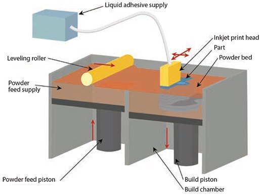
Invented at the Massachusetts Institute of Technology, powder 3D printers deposit a liquid binder solution from an inkjet onto a powder bed to fabricate 3D structures.1–3 The powder 3DP process begins by spreading a layer of fine powder material evenly across the piston. The X-Y positioning system and the printhead are synchronized to print the desired 2D pattern through the selective deposition of binder droplets onto the powder layer. After printing, the piston, powder bed, and printed part are lowered, and the next layer of powder is spread (Figure 1).

Figure 1. Illustration of powder 3D printing based on a series of steps that use a binding agent to secure powder in a 2D pattern, where the loose powder is removed after the part is printed.
The drop-spread-print cycle is repeated until the entire part is completed. Removal of the unbound powder reveals the fabricated part. Biomaterials such as peptides, proteins [e.g., fibrinogen (example Prod. No. F3879) and collagen], polysaccharides (e.g., hyaluronan and alginate), DNA plasmids, and living cells can be incorporated into the binder or processed as the powder for direct 3DP. Other previously used materials include synthetic polymers [i.e., poly (ε-caprolactone), polylactide–coglycolide or poly(l-lactic acid)] with an organic solvent as the binder and natural polymer powders [i.e., starch (Prod. No. 03967), dextran and gelatin (Prod. No. G1890)] with water as a binder. Currently used materials include ceramics [i.e., tricalcium phosphate, hydroxyapatite (Prod. No. 289396), and calcium polyphosphate], synthetic polymers (i.e., polyvinyl alcohol, PLGA, PCL), and natural polymers [i.e., collagen and chitosan (Prod. Nos. 448869, 448877, and 419419)]. To use these biomaterials, the biomaterials usually do not require special modification or functionalization, but they must be in a powder form. In vivo studies have been performed using these materials for the correction of bone defects (calvarial, tibia, femoral) in rabbit, rat, and mouse models.4–9 Alternatively, porogens such as sucrose (Prod. No. S7903), lactose, or table salt can be printed to create the desired shape. After polymer solutions are infused into the interstitial space, the dissolution of the porogens yields a 3D part of biopolymer.10
Fused-deposition Modeling
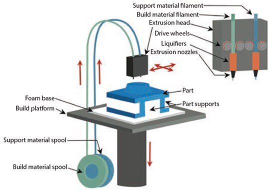
Fused-deposition modeling (FDM) is the deposition of molten thermoplastic materials in specific patterns using two heated extrusion heads that each include a small orifice.11 One nozzle deposits the thermoplastic material and the second deposits temporary material to support cantilevers (Figure 2). In one traditional FDM method, thermoplastic polymer is melted into a semi-liquid state and the head extrudes this material onto the build platform. The most important material selection criteria for FDM materials are heat transfer characteristics and rheology (behavior of liquid flow). In order to allow flow of the material for specific lay-down patterns, thermoplastics are commonly selected because of their low melting temperature. PVC, nylon, ABS, and investment casting wax have also been successfully used. For bioapplications, PCL is commonly used due to its low melting temperature (~60 °C), low glass transition temperature (–60 °C), and high thermal stability. Other materials used include PLGA, TCP (combined with a synthetic polymer), PMMA (Prod. Nos. 200336, 182230, and 445746), poly(ethylene glycol) terephthalate, and poly(butylene) terephthalate. Combinations of these materials are also used. This technology has been used in several in vivo studies, including animal models (e.g., murine animal models for wound healing and rabbit bone defects)12–14 and the treatment of a craniofacial defect in a human patient.15

Figure 2. Illustration showing the fused-deposition modeling process, where molten thermoplastic material is deposited in specific patterns.
Stereolithography
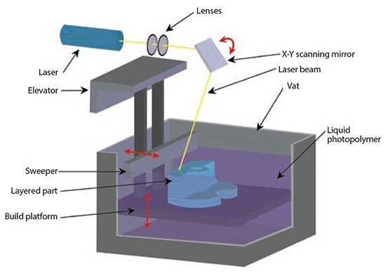
Stereolithography (SLA) was developed in the late 1980s and is regarded as the first rapid prototyping process.16 The original SLA method uses a rastered HeCd-laser beam to spatially control the polymerization of a photocurable resin in 2D patterns.17 After each layer is cured, the platform containing the cured structure is lowered (in the bottom-up approach) and another layer of uncured liquid resin spreads over the top (Figure 3). The topmost layer is ready to be patterned once the resin has spread. For the top-down approach, light is projected onto a transparent plate that is initially positioned near the bottom of the vessel holding the liquid resin. The build is detached from the transparent plate for each subsequent layer. Acrylics and epoxies are typically used in SLA; any materials used for SLA must include photocurable moieties for photocrosslinking. For tissue engineering applications, very few biodegradable and biocompatible biomaterials are dimensionally stable enough during photopolymerization for use in SLA. Over the last few years, more polymers have been synthesized that contain aliphatic polyesters that allow for biodegradation. The resulting macromer is then acrylated to enable photocrosslinking, for example, in poly(ethylene glycol) diacrylate. This trend has increased the library of available resins with biodegradable moieties and the encapsulation of cells during processing. These novel macromers include segments of PCL or poly(d,l-lactide), PLLA resins with modified end groups to allow for photocrosslinking capability, and PPF-DEF. In vivo studies have shown these materials can promote bone formation in rat cranial defects.18

Figure 3. Illustration of the stereolithography process using layers of liquid photopolymerizable polymers.
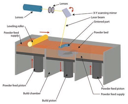
Selective Laser Sintering
1989.19 SLS is similar to powder 3DP in that powder particles are bound together in thin layers. In this method, however, a CO2 laser beam is used to bond the material by sintering.20 The laser scans the surface of the powdered polymer particles in a specific 2D pattern in order to sinter them above the glass transition temperature (Figure 4). During sintering, molecular diffusion along the outermost surface of the particle leads to neck formation between neighboring particles. After one layer is created, the piston containing the part is lowered and a fresh layer of powder material is rolled across the top surface. The subsequent layer is formed and bound to the previous layer. Unbound powder is removed after fabrication; the part is then heat-treated to achieve full density. Combinations of powders such as PCL and hyaluronic acid are commonly used. Biomedical applications of this technique include bone and vascular tissue engineering21 and inter-body cages for spinal fusions.22

Figure 4. Illustration showing the selective laser sintering process.
Three-dimensional Plotting/Direct-write Bioprinting
Three-dimensional plotting was developed at the Freiburg Materials Research Center in 2000 to create soft tissue scaffolds. This 3D plotting is based on extruding a viscous liquid material (generally a solution, paste, or dispersion) from a pressurized syringe into a liquid medium with matching density. The material is deposited in one long continuous strand or in individual dots from a nozzle or syringe to create a desired 3D shape of ceramics, polymers, or hydrogels.23 Similarly, bioprinting is the fabrication of hydrogel structures with direct incorporation of cells. This technology provides a controlled spatial distribution of cell or growth factors as well as the scaffold structures. Bioplotting materials include synthetic polymers and natural polymers such as collagen, chitosan, alginate, agarose, or gelatin. Most hydrogels compatible with cell bioprinting are ideal for implantation in biological environments that do not require high mechanical properties, such as cavalarial defects.24 Bioprinting has also been used to develop personalized cell-based chips to evaluate patient-specific drug response and cytotoxicity.25
Future Directions
Although there have been great strides in tissue engineering over the last five years, innervation and vascularization (the development of nerves and blood vessels within these tissues) of emerging tissues still remain very challenging. To achieve a fully functioning 3D-printed tissue that is integrated with the circulatory and neural control systems, functional gradients of cells and biochemical molecules must be created that mimic the conditions during embryogenesis and wound healing. Further, the deposition of cells requires materials and processing conditions that are fully compatible with biomaterials, unlike processing conditions with UV light, heat, organic solvents, or cytotoxic photoinitiators, among others. Incorporation of biochemical molecules necessitates the development of sustained growth factor release in controlled spatial-temporal release profiles. The creativity that now drives 3DP must be directed toward addressing these challenges in order for the field to evolve.
The outlook on 3DP for tissue engineering is extremely exciting. Technological advancements have made 3DP more accessible to those outside of industry and academia and allowed for more robust design and fabrication of scaffolds. New materials and methods are continuously being made to expand the applications of biocompatible scaffolds, such as using DNA sequences to place different types of cells in 3D to create organoid-like tissues (DNA-programmed assembly of cells or DPAC).26 This convergence is ideal to accelerate 3DP development to create the next generation tissue engineering structures.
References
To continue reading please sign in or create an account.
Don't Have An Account?